Sylvia Mirecki


What’s a 7 Segment Display?
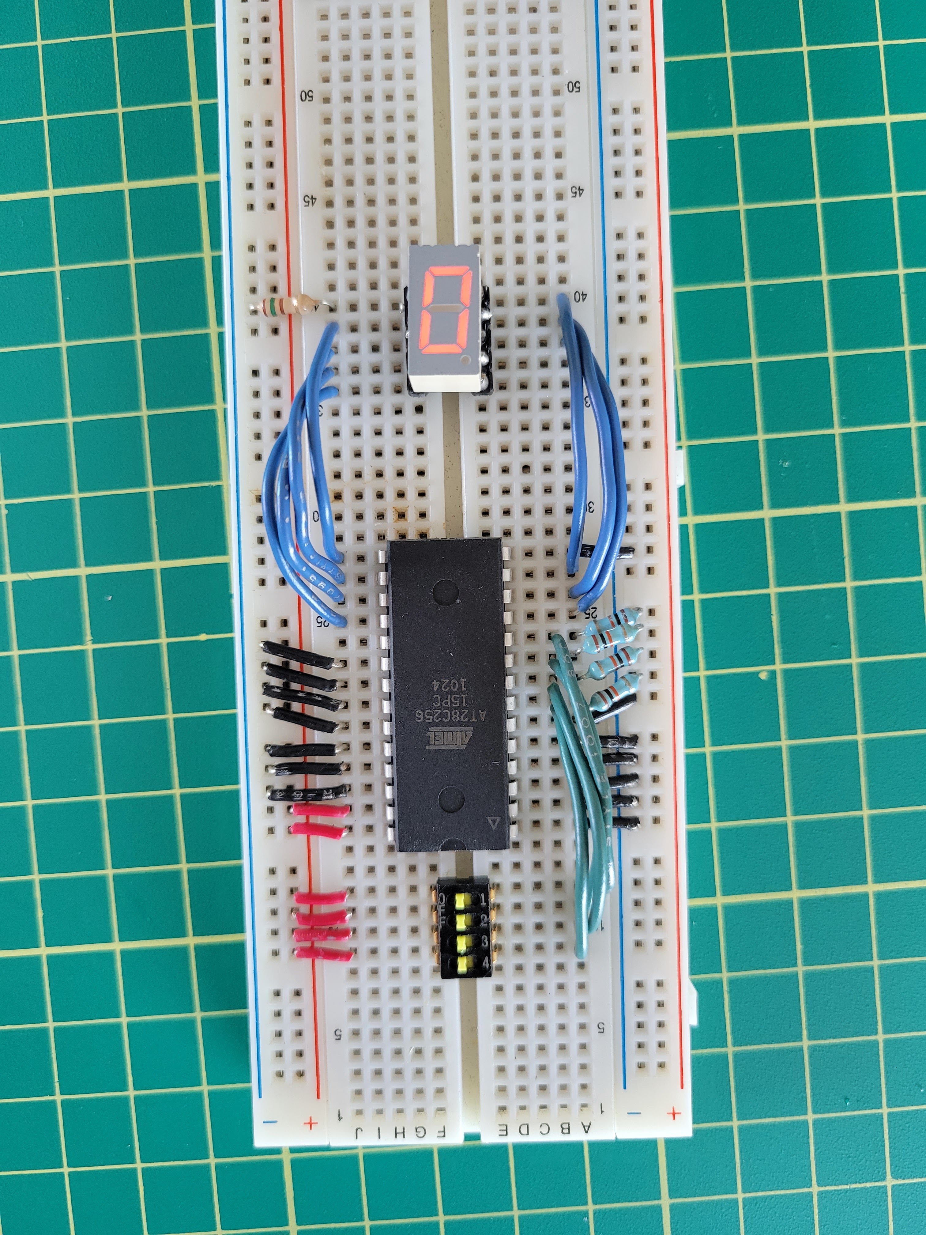
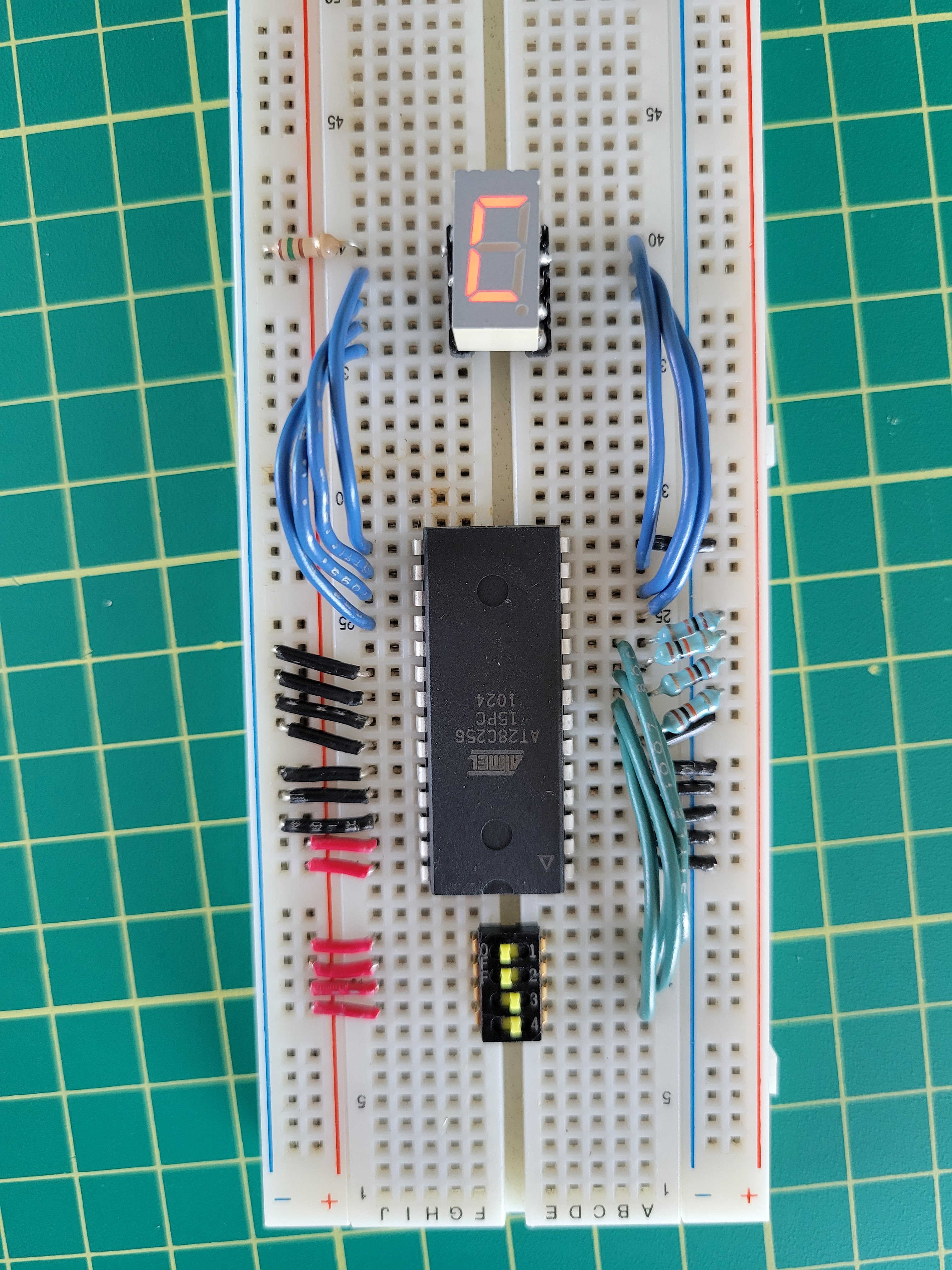
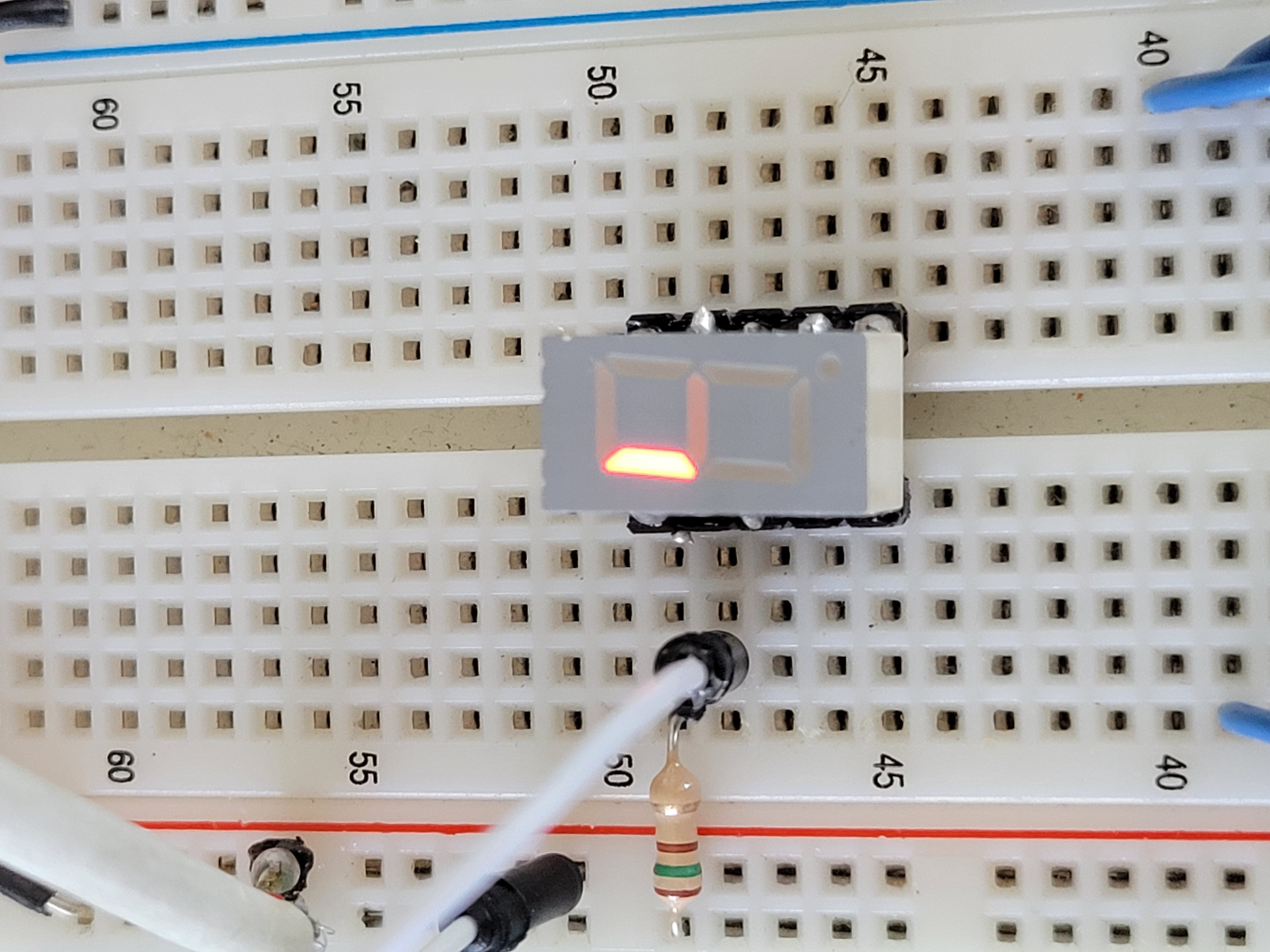
You’ve probably seen a display something like this before. They’re commonly used in alarm clocks, watches, microwaves, and other appliances. The one I found use a common anode, meaning the top left pin of the component must be connected to ground. When pulling other pins high, different segments will be given power.
As shown in the below two pictures, pin 4 is for the bottom segment, and pin 1 is for the top left segment.
Creating a Display Controller
I recently bought a 6502 computer kit, and thought about building some 7 segment display controllers for debugging. I heard about a hack where you can use an EEPROM as a lookup table for logic circuits. Since a 7 segment display only needs 4 bits of input, we could also use an EEPROM as a lookup table for a 7 segment decoder.
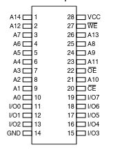
The kit came with a AT28C256 EEPROM chip, which has 7 address bits and 8 output bits. Meaning, it can store 32KiB of data. It’s a bit overkill for this use case, but works just fine!
To represent a single hex digit (a digit from 0 to f), you need 4 bits. So I only had to use the first 4 address lines of the EEPROM chip. I pulled the rest low so that only the first 16 byte of the EEPROM are used.
The I/O pins shown in the pinout are what I used to send power to the segments.
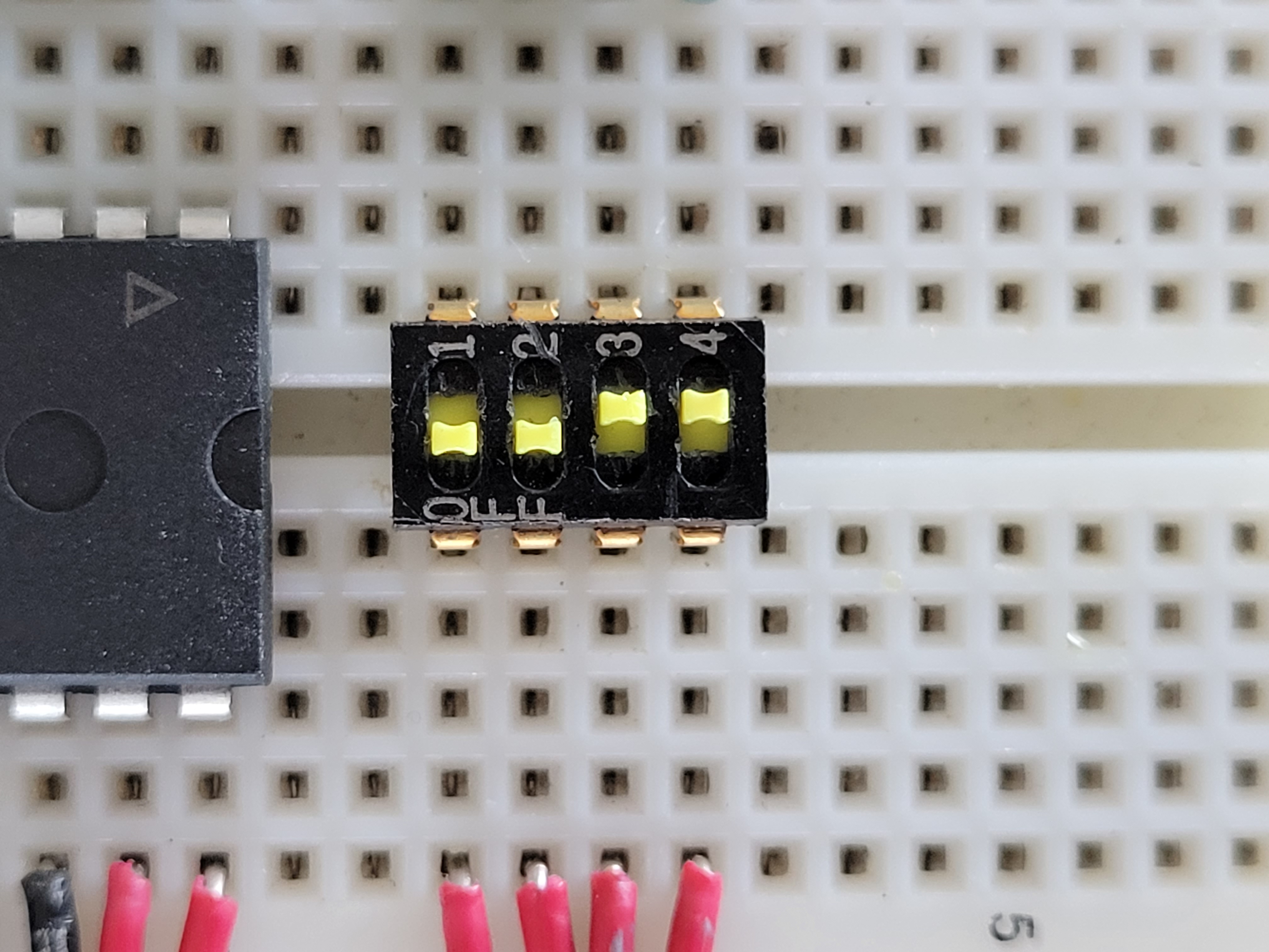
I also had this handy quad switch hanging around, which is perfect for testing out all the different inputs. I added 10k pulldown resistors to each switch to prevent the pins from floating.
Logic Mapping
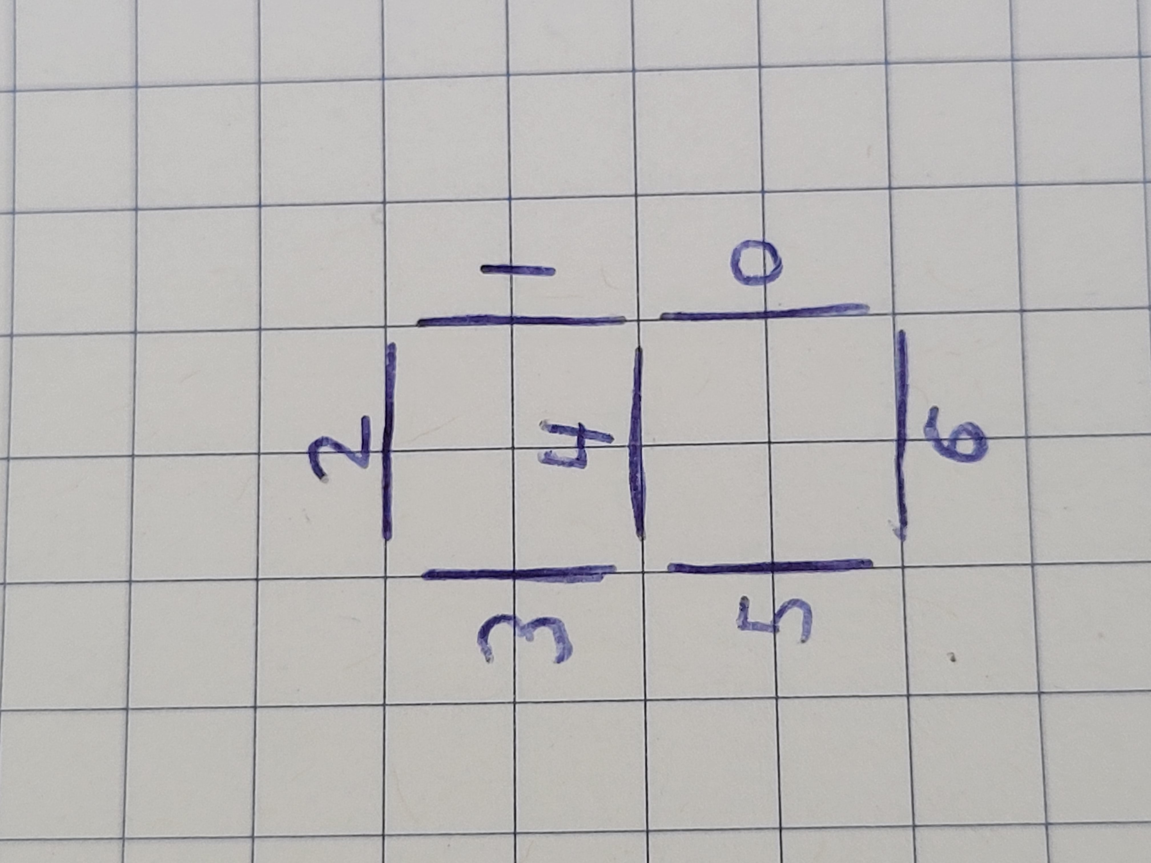
To figure out what values to output for each number, I first wrote down a mapping from each segment to the corresponding output EEPROM pin. Then I created a table of what segments should be on or off, represented as 1 or 0.
| digit | 0 | 1 | 2 | 3 | 4 | 5 | 6 |
|---|---|---|---|---|---|---|---|
| 0 | 1 | 1 | 0 | 1 | 1 | 1 | 1 |
| 1 | 0 | 0 | 0 | 0 | 0 | 1 | 1 |
| 2 | 1 | 1 | 1 | 0 | 1 | 1 | 0 |
| 3 | 1 | 0 | 1 | 0 | 1 | 1 | 1 |
| 4 | 0 | 0 | 1 | 1 | 0 | 1 | 1 |
| 5 | 1 | 0 | 1 | 1 | 1 | 0 | 1 |
| 6 | 1 | 1 | 1 | 1 | 1 | 0 | 1 |
| 7 | 0 | 0 | 0 | 0 | 1 | 1 | 1 |
| 8 | 1 | 1 | 1 | 1 | 1 | 1 | 1 |
| 9 | 0 | 0 | 1 | 1 | 1 | 1 | 1 |
| a | 0 | 1 | 1 | 1 | 1 | 1 | 1 |
| b | 1 | 1 | 1 | 1 | 0 | 0 | 1 |
| c | 1 | 1 | 0 | 1 | 1 | 0 | 0 |
| d | 1 | 1 | 1 | 0 | 0 | 1 | 1 |
| e | 1 | 1 | 1 | 1 | 1 | 0 | 0 |
| f | 0 | 1 | 1 | 1 | 1 | 0 | 0 |
ROM Generation
To generate the EEPROM ROM file, I used the following Go code. The main interesting part is program, which defines the ROM binary. It’s pretty much a 1:1 mapping with the above logic table.
package main
/*
 * This program will upload a ROM for decoding a nibble for a 7 segment display
 */
import (
	"log"
	"os/exec"
	"os"
)

var program = [32768]byte{
    0b01101111, // 0
    0b00000011, // 1
    0b01110110, // 2
    0b01010111, // 3
    0b00011011, // 4
    0b01011101, // 5
    0b01111101, // 6
    0b00000111, // 7
    0b01111111, // 8
    0b00011111, // 9
    0b00111111, // a
    0b01111001, // b
    0b01101100, // c
    0b01110011, // d
    0b01111100, // e
    0b00111100, // f
}

func main() {
    cmd := exec.Command("minipro", "-p", "AT28C256", "-w-")
	cmd.Stdout = os.Stdout
	cmd.Stderr = os.Stderr
    programPipe, err := cmd.StdinPipe()
    if err != nil {
        log.Fatal(err)
    }
    go func() {
        defer programPipe.Close()
		programPipe.Write(program[:])
    }()

    if err := cmd.Run(); err != nil {
		log.Fatal(err)
	}
}
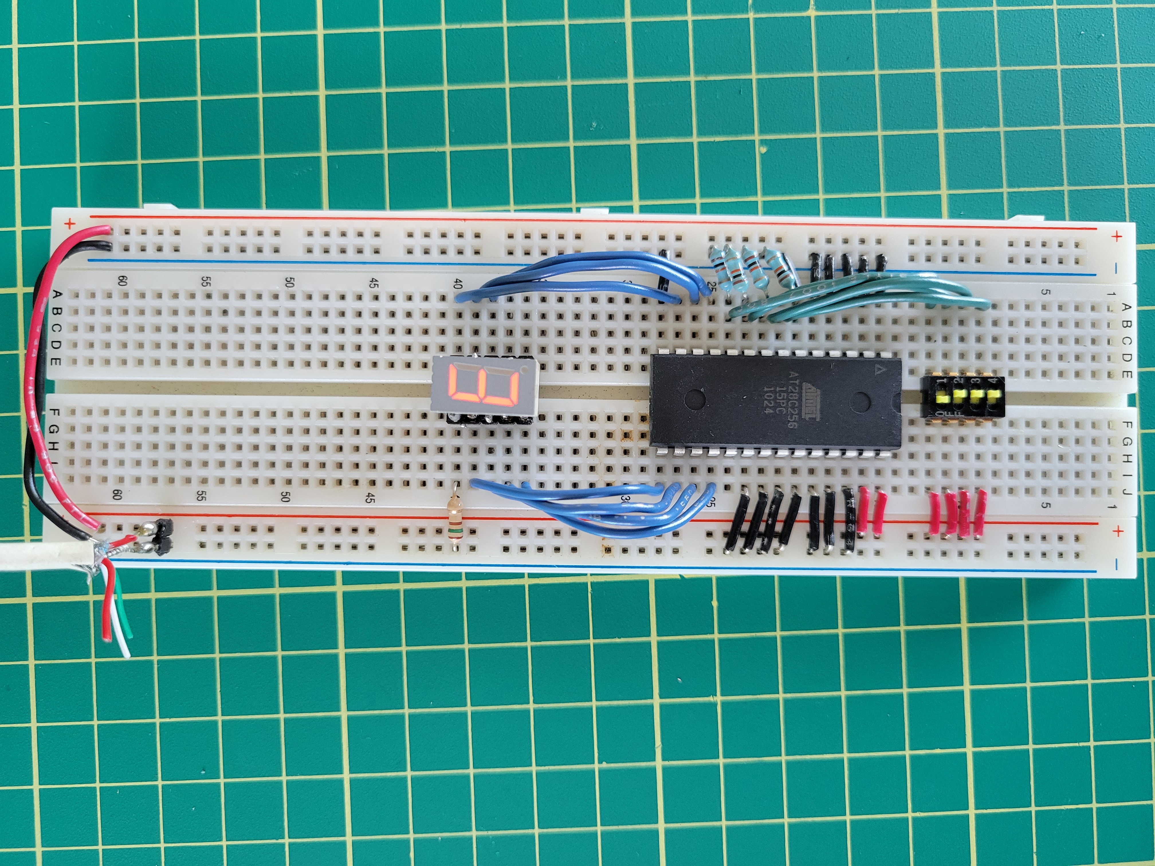
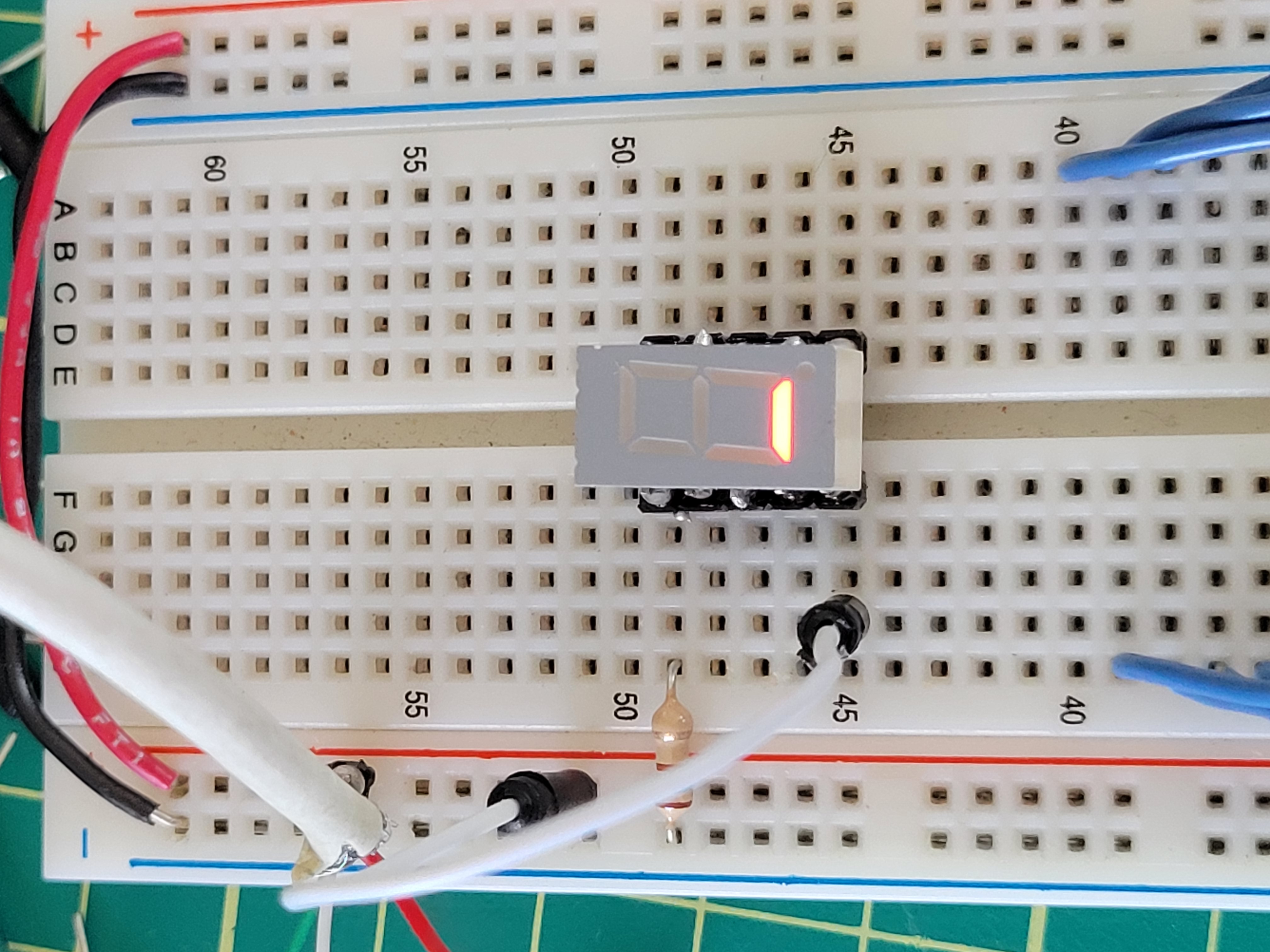
Finished product
And here’s the final result! Notice how the hex switch corresponds to the digit on the 7 segment display. I’m thinking about getting a few more of these EEPROM ICs, and creating a couple PCBs specifically for displaying bytes from the 6502 computer. We’ll see!